


All Products
-
Butt Weld Fittings
-
Stainless Steel Elbow
-
Stainless Steel Tee
-
Stainless Steel Reducer
-
Stainless Steel Pipe Cap
-
Duplex Stainless Steel Pipe
-
Stainless Steel Stub Ends
-
Forged Pipe Fittings
-
Forged Steel Flanges
-
API Carbon Steel Pipe
-
Stainless Steel Seamless Pipe
-
Stainless Steel Welded Pipe
-
Nickel Alloy Pipe
-
Hastelloy Pipe
-
Copper Nickel Tube
-
Stainless Steel Plate
-
Stainless Steel Bars
-
Spiral Wound Gasket
-
Cast Acrylic Sheet
-
 Brazil---AimeeIn the latest vendor rating, TOBO won the excellent rating, it is good, will continue to cooperate.
 -
Thailand ---Dave MulroyASTM A213 T9 Alloy steel pipe ,Stable quality , good price, excellent serive, TOBO GROUP is our trustworthy partner .
-
USA ---AlfaroASTM A182 F55 Super Duplex Flange ,Good quality , we like that ! And delivery time in time also ,very professional.
Forged Steel Flange CAD Drawing 3D Model with Bolt Torque Installation Guide


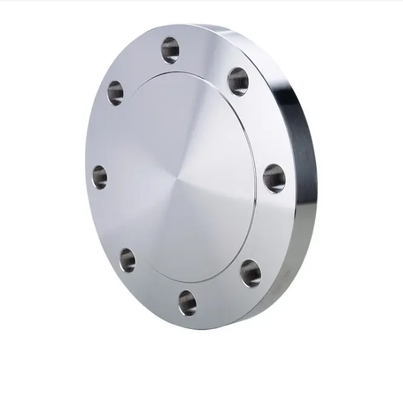
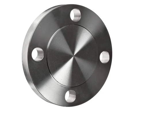
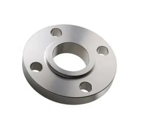
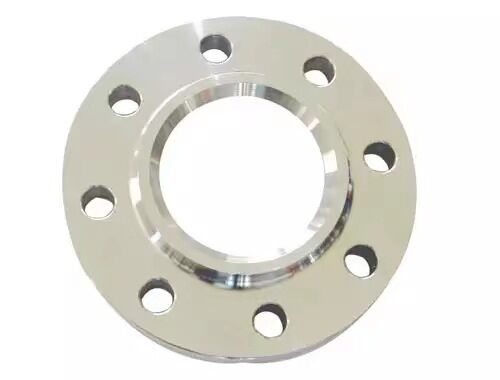
| Place of Origin | Hebei, China |
|---|---|
| Brand Name | SY |
| Certification | ISO 9001:2015 |
| Model Number | DOC-FL-002 |
| Minimum Order Quantity | 10 Pieces |
| Price | USD 5-50 / Piece |
| Packaging Details | Export-grade plywood case or pallet with waterproof wrapping and anti-rust oil protection |
| Delivery Time | 7-25 working days |
| Payment Terms | T/T,L/C,Western Union |
| Supply Ability | 50000 Pieces per Month |
Product Details
| Product Name | Forged Steel Flange With Technical Documentation Support | Documentation Type | CAD Drawing, 3D STEP Model, Bolt Torque Chart, MTC, Inspection Report |
|---|---|---|---|
| CAD Format | DWG, DXF, PDF Dimensioned Drawings Available | 3D Model Format | STEP, IGES, STL For Design Integration |
| Bolt Torque Chart | Provided For All Pressure Classes With Bolt Size And Target Torque Values | Material Test Certificate | EN 10204 3.1 Or 3.2 As Required |
| Inspection Report | NDT Report, PMI Report, Hydrostatic Test Report | After-Sales Support | Installation Guidance Via Email And Video Call Available |
| Highlight | CAD Drawing Flange Support,3D Model Forged Flange,Bolt Torque Installation Guide |
||
Product Description
Forged Steel Flange with Complete Technical Documentation Package
We understand that professional procurement engineers and project managers require more than just a product; they need comprehensive technical documentation to ensure seamless integration into their piping systems. Every forged steel flange from our production line is accompanied by a complete technical documentation package that includes dimensioned CAD drawings, 3D solid models, bolt torque calculation charts, material test certificates (MTC), and non-destructive testing (NDT) reports. This documentation-first approach reduces engineering review time, eliminates guesswork during installation, and provides full traceability for quality assurance audits.
Our technical documentation support covers the entire product lifecycle from design specification through installation and commissioning. During the quotation phase, we provide preliminary dimensional drawings to confirm flange dimensions, bolt circle patterns, and facing types. Upon order confirmation, we deliver certified as-built CAD drawings reflecting your specific material grade, pressure class, and facing requirements. The 3D STEP model enables your engineering team to integrate our flange directly into your piping isometric drawings and stress analysis models without manual recreation. After delivery, the bolt torque guide ensures proper gasket compression and eliminates the risk of under-torquing or over-torquing during field assembly.

| Documentation Item | Delivery Format | Application |
|---|---|---|
| CAD Dimension Drawing | PDF, DWG, DXF | Piping design and layout verification |
| 3D Solid Model | STEP (.stp), IGES (.igs) | 3D piping integration, clash detection, FEA |
| Bolt Torque Chart | PDF, Excel spreadsheet | Field installation and gasket compression control |
| Material Test Certificate | PDF, EN 10204 3.1 or 3.2 | Material traceability and compliance verification |
| NDT Inspection Report | PDF with scan images | Quality assurance and third-party audit compliance |
| PMI Report | PDF with alloy element percentages | Positive material identification for critical service |
| Hydrostatic Test Report | PDF with pressure/time chart | Pressure integrity certification |
| Installation Manual | Printed booklet and PDF | On-site assembly, welding, and torque sequence guidance |
Why Technical Documentation Matters in Flange Procurement
- Eliminates Dimensional Errors: CAD drawings with exact bolt circle diameter, flange outer diameter, raised face height, and hub dimensions prevent mismatched connections and costly field modifications
- Accelerates Engineering Review: Pre-verified 3D models reduce the time your design team spends recreating vendor parts, directly shortening project lead times
- Ensures Proper Installation: The bolt torque chart specifies lubricated and non-lubricated torque values for every bolt size and gasket type, preventing both leakage from under-torquing and gasket crushing from over-torquing
- Supports Regulatory Compliance: Full EN 10204 3.2 certification with third-party inspection satisfies PED 2014/68/EU, ASME B31.3, and other international pressure equipment directives
- Enables Lifecycle Traceability: Each flange is stamped with a unique heat number traceable to the MTC showing chemical composition, mechanical properties, and heat treatment records
- Reduces Project Risk: Complete documentation eliminates the risk of installing non-compliant flanges that could lead to catastrophic failure, regulatory penalties, or project delays
Frequently Asked Questions
Q: What CAD file formats do you provide and can I request custom drawing views?
A: We provide PDF dimensioned drawings as standard, with DWG and DXF formats available upon request. Each drawing includes front view, side section view, bolt circle detail, and flange facing detail. Custom views such as hub profile details, bore tolerance zones, and welding bevel preparation details can be added upon request at no additional charge. Typical turnaround for customized drawings is 1-2 working days after order confirmation.
Q: How do I use the bolt torque chart for field installation?
A: Our bolt torque chart is organized by flange size, pressure class, and gasket type. For each combination, it provides the recommended bolt size and quantity, bolt material grade, lubricated torque value (using molybdenum disulfide grease), and non-lubricated torque value. The chart also includes the recommended tightening sequence: three-pass cross-pattern tightening at 30%, 60%, and 100% of target torque. A final clockwise check pass is recommended to verify uniform loading. We also provide guidance on hydraulic tensioning for sizes above 24 inches where traditional torque wrenches become impractical.
Q: Do you provide EN 10204 3.2 certification with third-party inspection?
A: Yes, EN 10204 Type 3.2 certification with third-party inspection by TUV, SGS, Bureau Veritas, or Lloyd's Register is available upon request. This includes independent witness of mechanical testing, chemical analysis verification, NDT inspection, and dimensional inspection. The 3.2 certificate provides the highest level of independent assurance and is typically required for pressure equipment under PED 2014/68/EU Category III and IV, offshore projects, and nuclear applications. Please specify your third-party inspection requirements at the time of order to allow scheduling.
Recommended Products